Building for Boost - LS7 Dart
*In no way is this the only way to do an engine like this, there are other options, this is just one such engine*
Local customer wanted us to build a beefier engine for his procharged Corvette that could take more power and possibly more RPM than the OE short block that was in his car currently making around 1000whp. The idea was to run a bigger procharger later on and make more power further down the road when upgrading the head unit and intercooler system.
So lets get into the hardware.
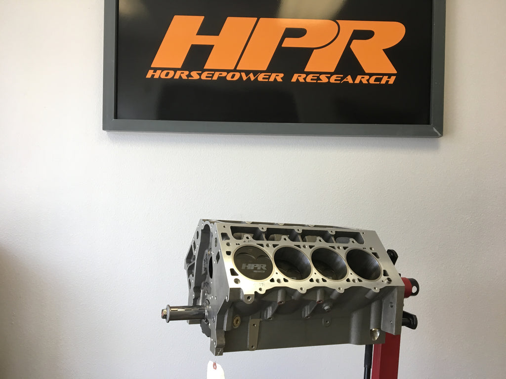
Engine Block

Not to go to a tall deck or billet block that couldn't run water, and would be stronger than the OE block sleeved we went to a full skirt Dart aluminum LS block. This did a few things for us. A revised primary main oiling circuit, billet splayed bolted main caps, larger cam core options, more lifter options, longer cylinders, thicker deck, better material. Not only could we do all of this but it was lighter than the typical GM LSx cast iron block or Dart SHP iron blocks that would add even more weight to the car.

Over the typical surface / line hone / and cylinder finish we had to do some additional work to the block.


Given we knew we were going to go boosted and were shooting for 1500+ hp to the tires we wanted a more stable crankshaft so machine work was done for clearance on the center counter weights. Cam journal was up-sized from 55mm to 60mm using conventional cam bearings, lifter bores were taken from 0.842 up to 0.937 diameter units and lastly head studs sized for 1/2" hardware.
Crankshaft / Connecting rods / Pistons
Speaking of crankshafts, like other big HP engines you have seen us do in the past we really like to use Bryant Racing as they are one of, if not the best crankshaft manufacturer in the US. This billet piece offers us full width, 8 counter weights with their super finish to cut down on oil drag and windage. We retained in this application OE bearing sizes on the mains as well as the rods.

For our connecting rods we are using off the shelf Callies Ultra H beam connecting rods that will be holding onto custom designed HPR pistons made by Wiseco.

Not always required, but it is nice to do a hard anodizing to the pistons. While it does not make them burn proof it does greatly harden the ring lands so the rings do not want to stick as easily and it helps deter damage caused by knock. It does not make them foolproof so things can still go south if the tuning is not correct but just adds a margin of safety during the build. Rod bearings are coated and we are running a thicker wall, tool steel wrist pin. Pistons will be using a custom set of rings by Total Seal.
Short block
Once the block has been machined, de-burred, and checked we wash it and wipe it down with oil for assembly. First is main bearing clearance followed by setting the crank in place (crank is already balanced at this point). When installing any crankshaft, always make sure to check and set thrust. Which you have seen us do in other builds. Given the Corvette has a re-mounted torque converter it will not directly be bolted on the end of the crankshaft so in this application we did not feel the need for any special roller thrust bearing as you might have seen in the turbo Dart build.

Here you can see thrust is being checked in the block with the caps removed. It is constantly checked as the caps go on and get torqued in place. #3, the trust cap is the last one to be installed. Any issues in loss of thrust will have to be addressed and corrected as the caps go on.
Rings are file fit, cleaned and installed. Rod bearings checked for clearance as is the wrist pin clearance on the rod and on the pistons. Everything is washed again, and assembled for install into the block.

Once all rods and pistons are in, caps are torqued on the rods and we go about final checks on deck height, piston rock, break away torque, and rolling torque on the engine before it is stored prior to long block assembly (if we are waiting on parts at the time).
Heads
A set of Brodix BR7-BS LS7 heads were picked for this build so we could use the larger valve size, better port angle, and better selection of intake manifolds. These have been ported by West Coast Cylinder head before coming back to us for prep and assembly.


Valves are 2.250 Titanium intake and a 1.600 inconel exhaust. Weights shown and we wanted to use a light-ish valve to keep it stable above 7000 RPM.
With the aid of some custom parts and machine work we were able to use Comp Cams new dual conical valve spring and Ti retainers. Speaking to Comp about this project combined with the lobes we are using and lighter valve train parts we feel this will be a good test for the dual conical setup.

Cam and Lifters
As stated early on we are going to a larger camshaft core and increasing the journal size to 60mm to allow for a larger base circle and stiffer cam core.
While 5mm doesn't sound like a lot, it will greatly reduce the load on the cam bearings as well as reduce deflection in the valve train. Here you can see the 60mm vs a stock OE 55mm.


*TECH TIP*
When you switch cam cores, and change lifters, and change blocks from OE, you need to make sure your lifters can properly get oil not only at the base circle but also at full lift. The first time we checked this, we noticed that the lifter cut off the oil passage way at full lift. Luckily we were using a test Jesel lifter so when we placed the order for the real lifters to be used we noted this to make sure the oil band on the new lifters would allow oil flow through the cam oil journal at all times.

Here you can see the oil band on the lifter when the lifter is on the base circle.

Here it is at full lift and all but just a very tiny sliver has now been covered up blocking all oil to the other lifter. The actual lifters, have a much wider oil band allowing oil flow at all times.

Speaking of lifters....
Larger than your normal 0.842 lifter we again went bigger to a 0.937 tie bar lifter with offset pushrod cups. This allows us to straighten up the pushrods in the engine, run a bigger wheel on the lifter (0.850 vs 0.700) to help reduce the stress and friction on the camshaft lobes. Many times we have all seen pitting, and damage done to the cam lobe as well as failed axles and wheels. Sometimes this can be by improper valvetrain setup, sometimes it can be to aggressive of a cam for the smaller lifters or a combination there of. Since we are going solid we wanted a better lifter than stock so why not go with the best, Jesel. These are DLC coated tie bars made with a double 0.150 offset on the pushrods and larger axles.

Once we had the camshaft in, noted what we needed to do on the lifters the cam is then degree'd and locked in place.

Before the heads can be assembled for good there are a few more items to check off the list. 1. P to V measurements, 2. rocker stand height, 3. pushrod clearance, 4. deflection in the system.

Not always right the first time out of the box (i.e. you still need to run a pattern), the Crower kits come with a cool checking tool to allow you to setup your rocker arm stand height based off the valve length and lift of the cam. Here you can see two shims leveled out the tool.

Here the head is tightened in place with the stand now setup so we can mock up for P to V check using the checking springs and also check the rear lift, and pushrod clearances.


As you can kind of see in this picture, the pushrod is a little to close even with the smallish 3/8" pushrods so we will have to mark and machine the pushrod holes to aid in clearance of the larger diameter ones we want to use. This also means machine, clean, mockup and check again before final assembly.
Fast forward to machine work, clean, checking again...now we again set it up with the checking springs as well as a pair of the real springs so we can confirm lift and rocker arm ratio and note the changes from the checking spring to the real spring to see how much things move.

Why you ask do you do all of this?

This is why. On paper we have a 1.8 ratio rocker arm, 0.440 intake lobe and 0.441 exhaust lobe. This should give us 0.792 intake and 0.794 exhaust valve lift. When setup and measured on the engine with the checking spring we are seeing 0.837 intake, and 0.835 on the exhaust. So given the change in wheel size, and any additional ratio they build into the arm we have roughly a 1.9 ratio rocker arm. Now for the fun part. Using the same head, moving to the real springs we see a drop down to 0.807 on the intake and 0.800 on the exhaust. About a 0.030 reduction in lift with zero lash, meaning the system is deflecting that much. Take out the 0.014-0.016 ish of lash and we are actually about what the cam card said it would have been to start with. This is why real data matters, on the actual engine, using the actual parts. Not looking at this you can have valve springs running into bind issues, valves crashing into heads...any number of things. So for about the 4th time now we can pull the head back off, clean it for a final time and start spring setup and get to assembly.

First step is always check install height.

Clean, lube, and install your springs, retainers, and locks.
Final wipe down and install onto the block with proper hardware, lube, and torque specs.


Stands can go on for good now, and rockers pre-oiled before installing pushrods and bolting down rockers.

Rockers set with a rough lash by feel. All arms installed and torqued in place before going to final lash adjustments.

Getting ready to set lash, torque the adjusters before capping off with Comp's new billet LS valve covers.