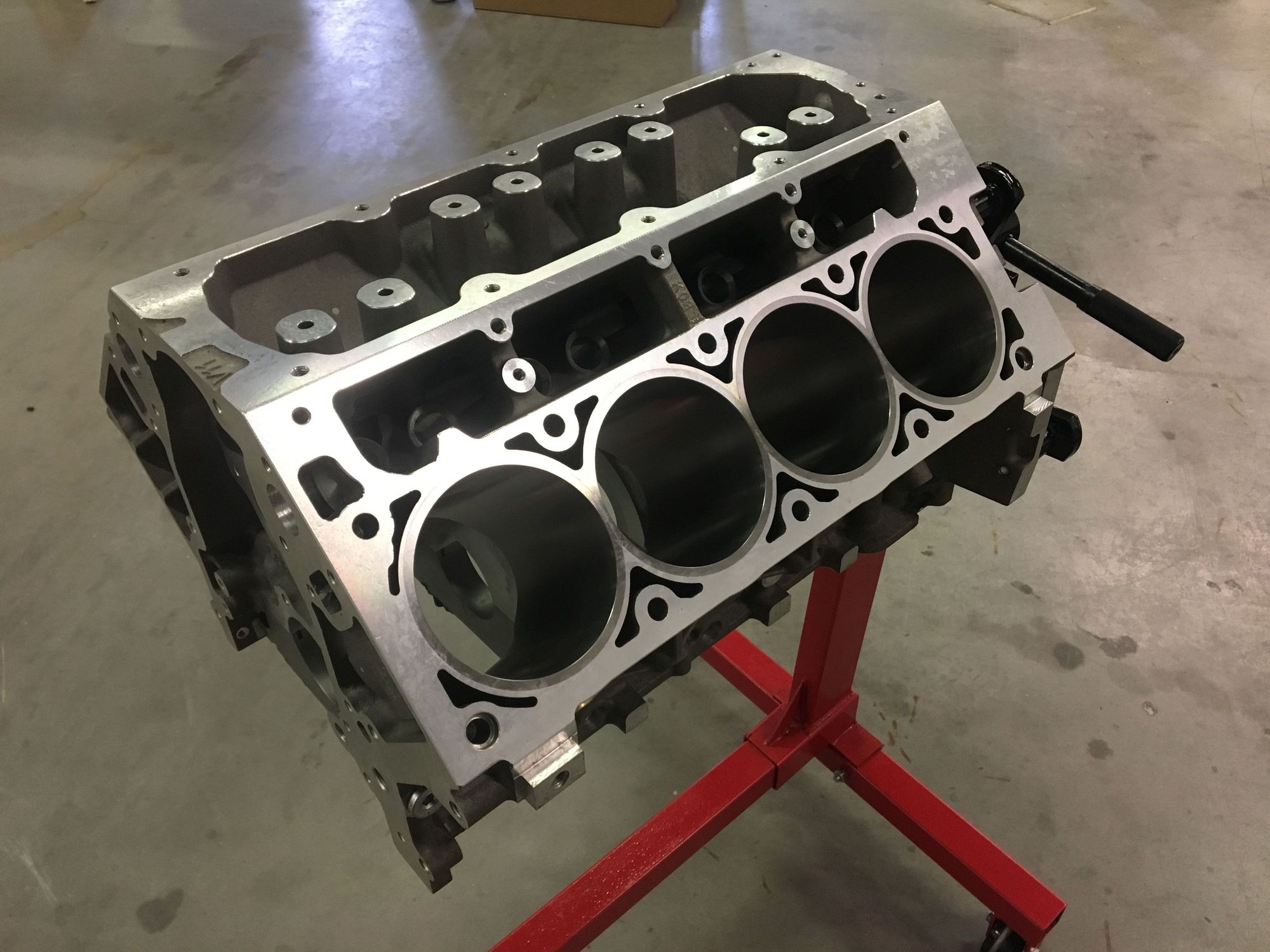
Why is the casting so important you might ask? Well let us take a closer look.
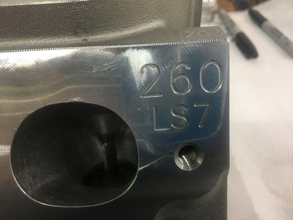
For the purpose of this article we are going to be looking at LS7 based heads. This does apply to other cylinder heads too, but given most of our engines are LS based and the LS7 being top of the list on power that is what we are going to be using here.
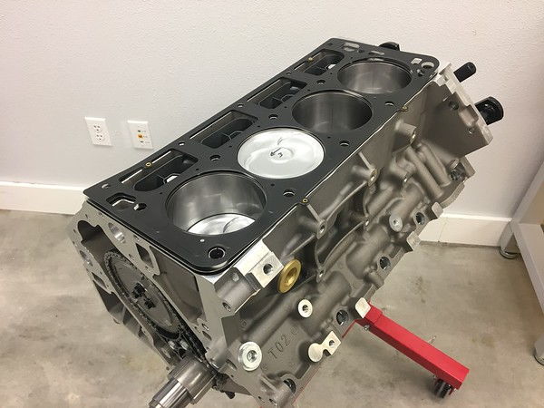
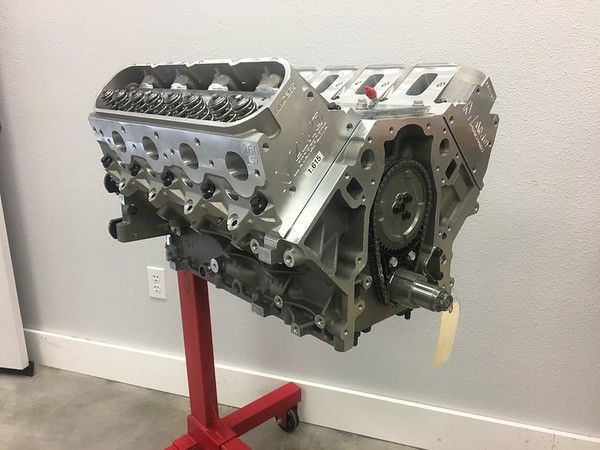
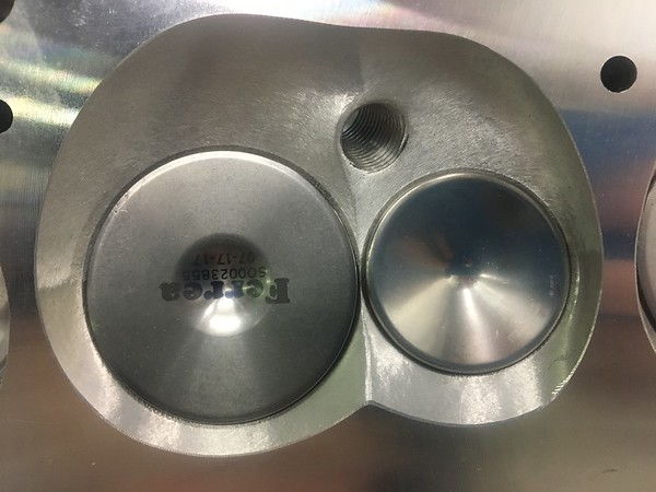
OE and OE type heads.

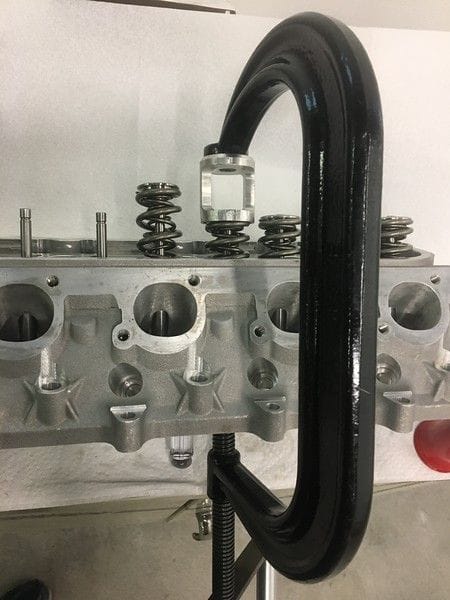
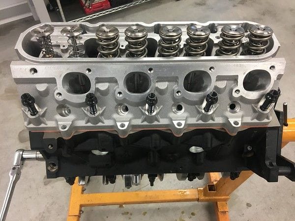
Take this Brodix BR7 cylinder head that we offer. Like the OE head it has cast in rocker pedestals for them to be bolted down to. These heads will accept a number of OE and OE replacement rocker arms and OE length valves. By doing so the geometry is locked in place and you can 'set it and forget it' in a manner of speaking. As long as you are within the acceptable limits of your rocker arm everything works out pretty well. These will use an 8mm hold down bolt and everything fits under a OE valve cover.
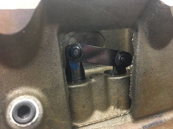
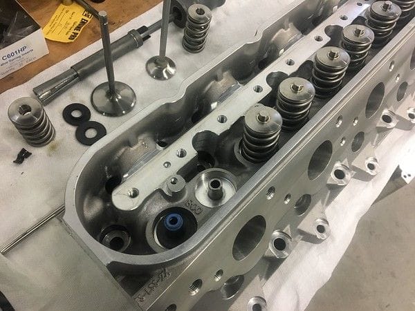
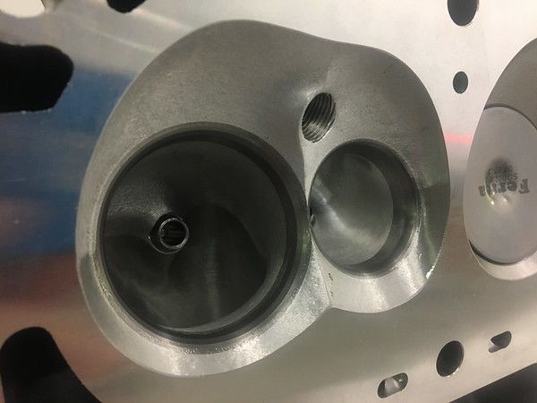
For a hyd roller system, this is a very good layout. Why you might ask? For one the pedestals are cast into the head itself. This gives it a way stronger and thicker support than what you might find on a LS1/2/3 head that uses the bolt in stands. All of that load can be spread out further into the head to keep the rocker stable. Now you might have seen some shaft mount rockers from Comp and BTR that further tie all of this together

By doing this now we can better connect and send that load out across the rockers which can and does help.
So why couldn't this cylinder head be used on all applications??

*Pic courtesy of MotorTrend
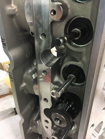
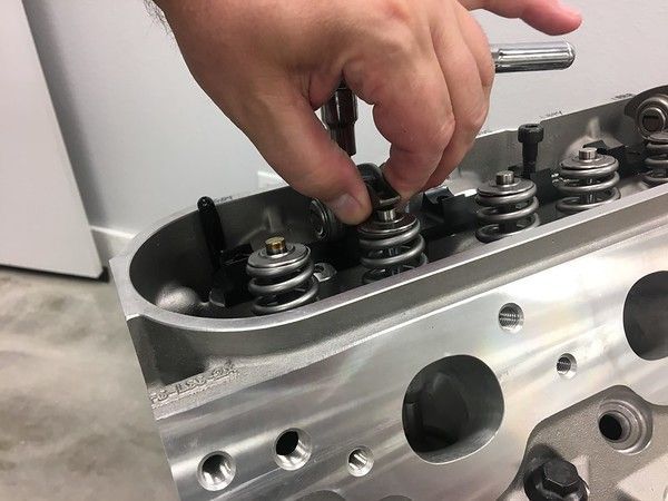
Let's look at the rocker arm. As we go up in ratio, distance A is always greater than distance B. So the pivot arm is not in the center of the rocker arm, this can and will create a bending motion around the hold down bolt. As we go up in RPM, lift, and spring rate we are going to be putting more and more force on that hardware to try and RIP it out of the head. 
*Pic courtesy of CorvetteForum
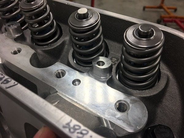
While that isn't the only reason something like this can happen, when you push lift higher and higher as well as the necessary spring rates to control a solid roller you can push it past the breaking point.
This is also why we do not suggest, nor will we modify a OE style head to run a shaft mount rocker arm system.
SO WHAT DO YOU DO???
Well, I'm glad you asked because a lot of cylinder head companies offer something just for this. 
*Brodix BR7 - BS head

*Frankenstein F710 head

*CID LS7 Oval port
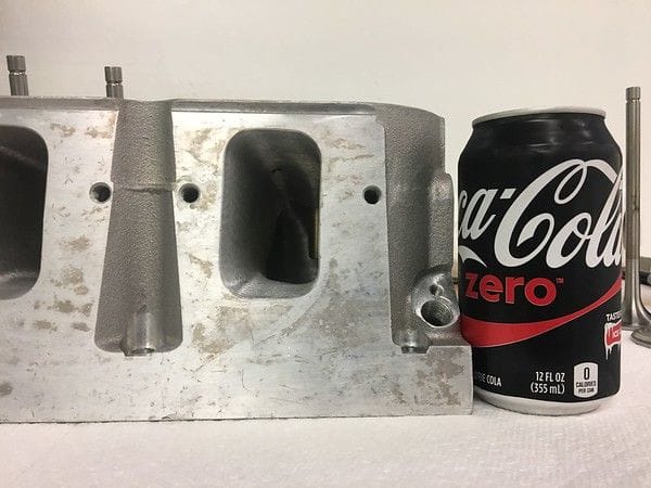
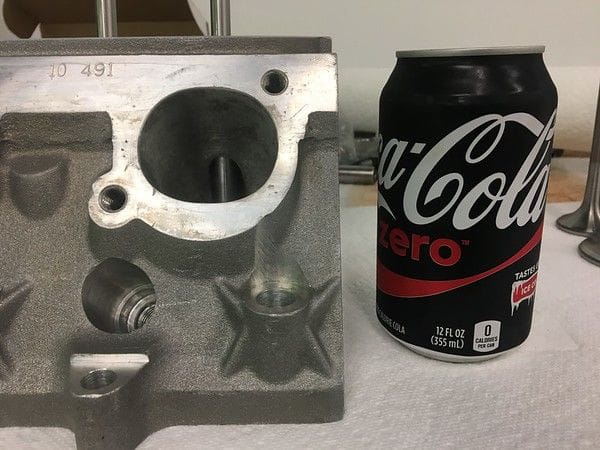
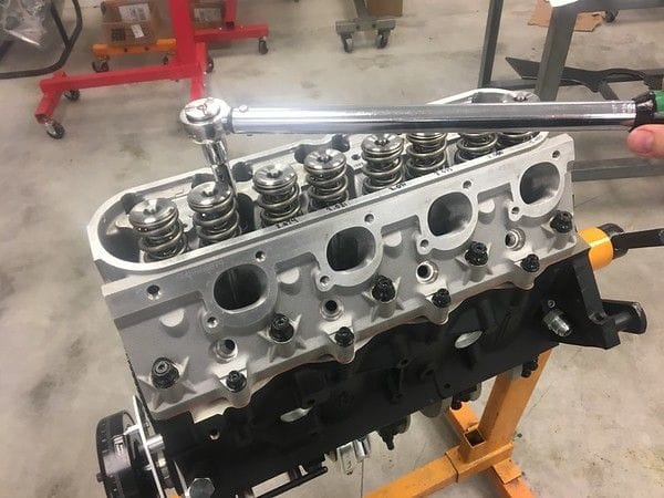
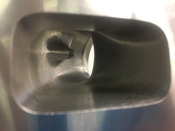
The three heads shown above are some of the most popular current offerings in the LS market for serious engine builds. Each will have their own benefits and key features but for now we are only looking at a few keep points. One of the first things you should see is that they lack any kind of rocker arm mounting point. Rather you have a very large, wide, flat base in which to mount a steel rocker arm stand to. Not only are you going to be bolting this to the head itself but rather than the small OE 8mm bolts these are massive 7/16" bolts in either a straight line, or a offset pattern to keep that stand bolted as firmly as possible to the head to keep it from wanting to rock as the valves are opened and closed. 
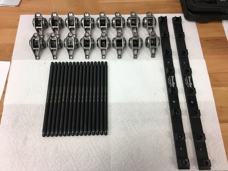
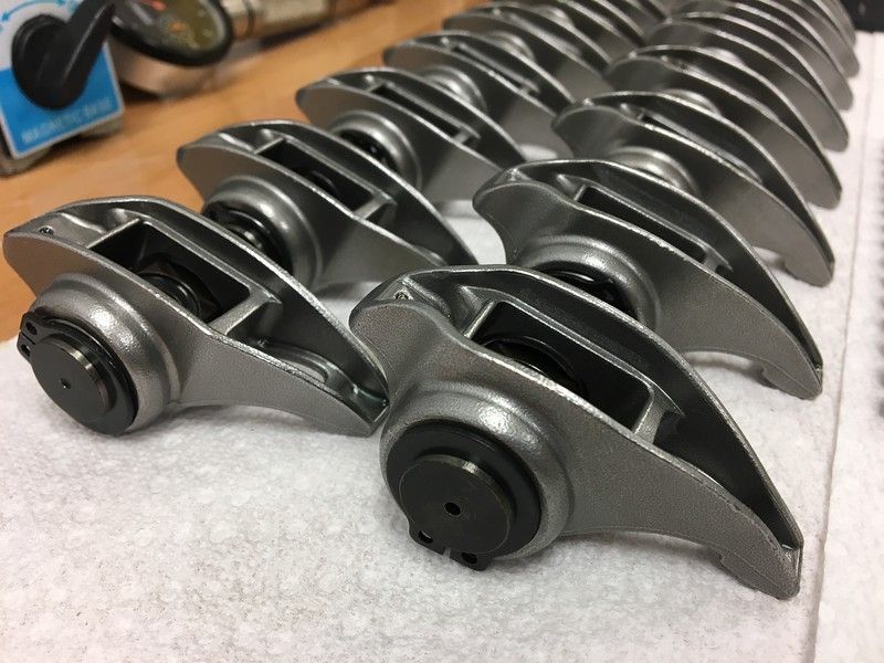
*Crower stand system for All-Pro, Brodix, MAST style heads

*T&D system for CID heads.
As you can see these stands go the full length of the cylinder head and offer their own mounts for the rocker arms themselves. This also allows them to either use offset rockers, OR the ability to roll the rocker around to clear the intake port and keep the rocker with as minimal offset as possible to keep the forces more in a straight line. Something that you can't do with a OE head.
Why does this matter?
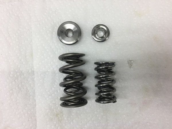
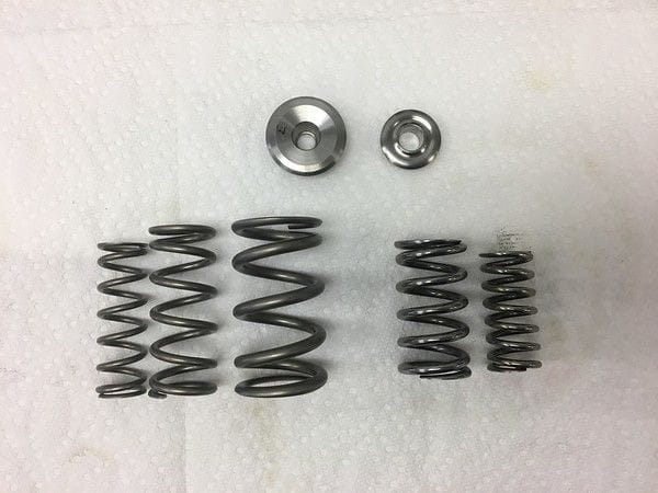
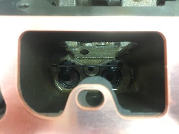
Probably the two biggest reasons are lift and spring rate. As you change the lift of the setup the geometry can and will have to change. If we are building a engine for 0.800, 0.850, 0.900 or more lift we need to not only have longer valves but we also need to be able to adjust the height of the stand to better dial in how the rocker arm is acting on that valve. Being able to do this on a OE casting and keep the rocker system stable is something that just doesn't happen outside of very low lift, low pressure setups.
The other issue is spring rates. Remember those little 8mm rocker arm bolts on your OE head? You might see 85-100lbs on the seat maybe 290-350lbs open on a OE type spring and as much as 150-200lbs on the seat and 400-500lbs open with a aftermarket setup. Solid roller spring rates are going to be far greater than that most of the time. While well sorted systems using light parts might still be in that 150-200lbs on the seat some can have as much as 200-300lbs seat pressure and 650-1200lbs OPEN! These loads get directly translated into the base and cylinder head so you want to make sure that you have a very stable and locked down assembly so as to not cause unwanted movement in the system.
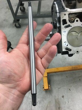
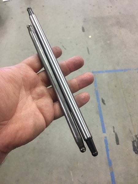
If you recall from a prior post, just how much bending is going on in these systems even with a big stand and bolts.
https://horsepower-research.com/blogs/news/rocker-arm-ratio-spring-rates-lash-deflection-what-is-my-lift
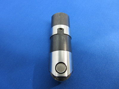
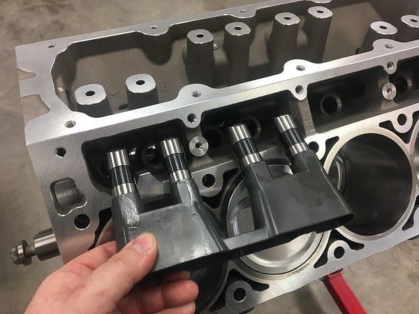
Of course there is way more to picking the correct head for your particular application but the style of lifter you will be using plays a HUGE roll into what cylinder head casting we will start with to make sure you have the absolute best results and reliability.


.")


 (more on that later).