
HPR TT LSx Build Thread Part II
#2 Thrust
High HP builds can place a lot of stress on internal components of the engine. Many of us think to forged pistons, or better connecting rods but something that might be overlooked is as simple as thrust.
All engines have some thrust pressure against them, be it from a simple stock clutch or big stall converter. This is one reason you need to take steps during the assembly process to measure thrust and make sure it is enough for your particular build process.

checking thrust - pic for example only - not the engine in the build
You check thrust just after the crankshaft is placed in the block to see how much movement you have. To much and you inspect bearings and the crankshaft for issues, to little and you again..inspect and correct. Install all caps, other than thrust and measure again, install thrust bearing/cap measure before and after the cap is tight. All of this is done to make sure the crank has enough clearance to maintain oil between surfaces when it is loaded. This distance can vary again depending on transmission type, engine use and the loads it is going to see.
The problem can lie however, when loads exceed what this small amount of oil and bearing surface can handle. While LS engines have 5 main bearings to support the crankshaft in rotation there is only one small surface to keep the crankshaft from moving to far fore or aft. Big stall converters, and a lot of HP can quickly lead to excessive pressure on the crankshaft and damaged / spun thrust bearings. So what are you to do?
You could increase the space, or modify the bearing to allow more oil but this in turn will create an internal oil leak and drop oil pressure to the engine causing other issues.
One of the ways to go about solving this issue is using a roller thrust bearing in addition to the standard thrust. In this build we felt the roller front thrust will give us the protection needed to not spin the normal thrust and keep clearances closer to normal as to not create an oil pressure issue.
Below you can see the roller thrust as it is installed on the nose of the crankshaft itself.
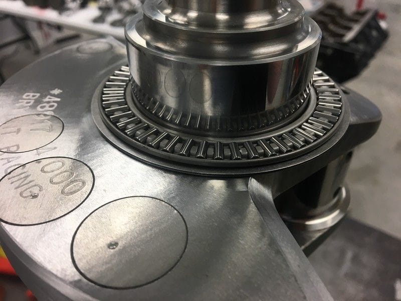
base plate and rollers installed
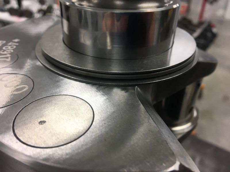
complete roller thrust assembly
In order to do this, the crank must be setup for it, and the block must have special machine work to the block and cap as you can see here on #1
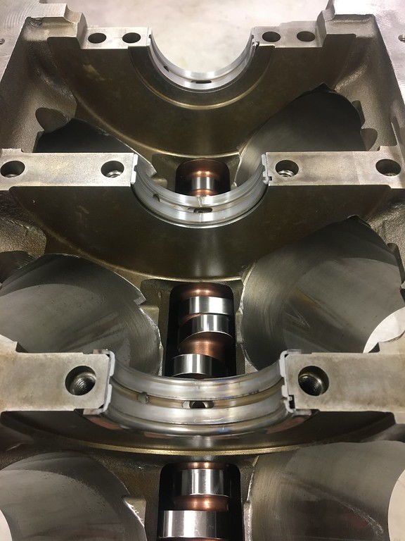
#1 main area cut for roller thrust bearing
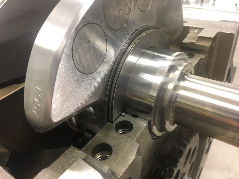
Roller installed
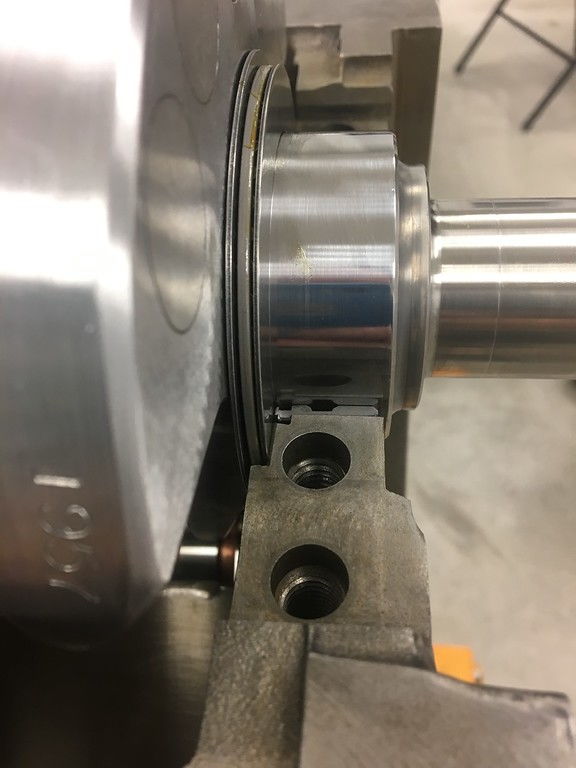
Shown here with the cap removed of course so you can see how it fits down into the block itself.
Of course this now requires much more time to setup as you have two surfaces to measure and check during install but in the end you have a much more reliable design to maintain crankshaft location in the engine block itself and less chance of bearing issues.
High HP builds can place a lot of stress on internal components of the engine. Many of us think to forged pistons, or better connecting rods but something that might be overlooked is as simple as thrust.
All engines have some thrust pressure against them, be it from a simple stock clutch or big stall converter. This is one reason you need to take steps during the assembly process to measure thrust and make sure it is enough for your particular build process.
checking thrust - pic for example only - not the engine in the build
You check thrust just after the crankshaft is placed in the block to see how much movement you have. To much and you inspect bearings and the crankshaft for issues, to little and you again..inspect and correct. Install all caps, other than thrust and measure again, install thrust bearing/cap measure before and after the cap is tight. All of this is done to make sure the crank has enough clearance to maintain oil between surfaces when it is loaded. This distance can vary again depending on transmission type, engine use and the loads it is going to see.
The problem can lie however, when loads exceed what this small amount of oil and bearing surface can handle. While LS engines have 5 main bearings to support the crankshaft in rotation there is only one small surface to keep the crankshaft from moving to far fore or aft. Big stall converters, and a lot of HP can quickly lead to excessive pressure on the crankshaft and damaged / spun thrust bearings. So what are you to do?
You could increase the space, or modify the bearing to allow more oil but this in turn will create an internal oil leak and drop oil pressure to the engine causing other issues.
One of the ways to go about solving this issue is using a roller thrust bearing in addition to the standard thrust. In this build we felt the roller front thrust will give us the protection needed to not spin the normal thrust and keep clearances closer to normal as to not create an oil pressure issue.
Below you can see the roller thrust as it is installed on the nose of the crankshaft itself.
base plate and rollers installed
complete roller thrust assembly
In order to do this, the crank must be setup for it, and the block must have special machine work to the block and cap as you can see here on #1
#1 main area cut for roller thrust bearing
Roller installed
Shown here with the cap removed of course so you can see how it fits down into the block itself.
Of course this now requires much more time to setup as you have two surfaces to measure and check during install but in the end you have a much more reliable design to maintain crankshaft location in the engine block itself and less chance of bearing issues.