
HPR TT LSx Build Thread Part V: Valvetrain
#5 Valvetrain
Because this is going to encompass the valves, rockers, heads, gaskets.....this update is going to have a lot of material thrown at you all at one time. So much of the next steps tie into the next part more so than earlier so bare with us.
The cylinder heads and valve train can sometimes turn into a mystery for a lot of people on their builds. There are a number of steps that you can take to try and cover as many basis as you can if you are trying something new but it does boil down to having a combo that is proven and tested to work together. Picking pieces here and there sometimes can result in very poor performance even though each individual part can be quite good....they just might not work well together.
Some points of this section I will not go into great deal with spec wise as to this particular build.
So off we go..
Camshaft

Camshaft installed
For our purposes within the LS market there are really only two types of camshafts. Solid roller or Hydraulic roller. As you have seen in prior updates on the lifters you already know this is going to be a solid roller profile camshaft. Some of you might know that you can also pick from a traditional style babbitt bearing or go to a roller bearing. You can typically also go larger on the camshaft diameter. In this case we went with the traditional style babbitt but did increase the core size up from 55mm to 60mm to increase the camshaft stiffness due to the pressures it is going to see.
Cam Drive
There are a number of ways the camshaft can be driven and timed to the crankshaft. The most common way for a traditional American V8 has been the timing chain. Of course there are different styles from non adjustable to adjustable, single or dual row chains. There is the every popular gear drive with the hot rodders that love the whine of the gears at speed and almost zero slack in the system. However with high RPM and race use engines, the belt is still one of the best ways to go. These tend to dampen out some harmonics and give an almost shock absorber application when running extremely high spring pressures. Because of the solid roller, high spring pressures, high RPM use and the face that we would like to be able to make adjustments to cam timing....a Jesel belt drive will be used on this engine.
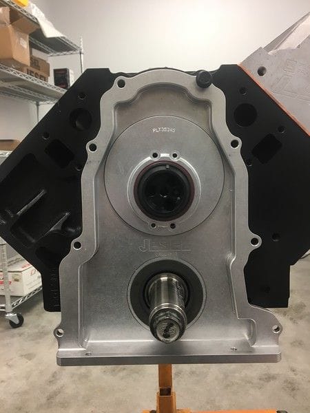
Jesel belt drive front cover
You can see the bolt pattern of the Jesel is exactly the same as any LS front cover so the system can be used on almost any number of LS engine blocks, given you take the time to machine the front of the block for clearance for the cover to fit.
There are quite a number of parts included in the system.
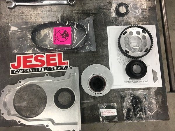
Jesel belt drive
Below you will see the final assembly installed waiting on the balancer.
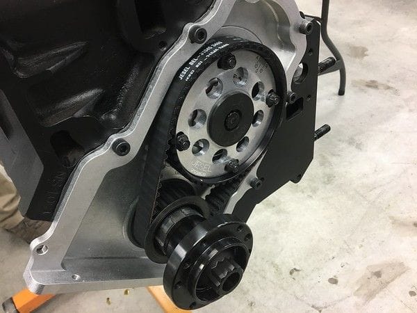
Belt drive installed along with ATI drive hub
Now you might be asking why not run a belt all of the time? Well they do stretch over time and will have to be serviced. In this case they are exposed to the elements so street use where rocks and debris can damage the belt and pulleys would not make it the best choice for a daily driver. For most builds out there, a chain is still the best of both worlds. The other piece to notice when applying this to an LS engine, there is zero room for an "internal" oil pump. When using the Jesel the engine must be a dry sump oiling system.
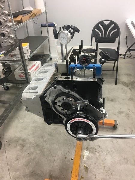
Timing is very critical on not only degreeing in the cam but also the balancer. Before the driver side head is placed onto the engine, we must make sure the timing marks on the balancer are correct and that we have the cam timing that we would like to see and locked in.
Cylinder Heads
Here we could devote an entire book on, so we are not going to go into who's head is better than who's or the details of head porting. Cylinder heads in many ways are one key item in to knowing how much an engine will make, at least NA wise. The size of the intake valve, the intake runner size, and how much CFM it can actually flow will give you a good idea of what the potential of the engine is. Air flow velocity must also be taken into account along with the total air flow. This one is slightly different in that we are force feeding it, but never the less, the heads have to be able to flow air. So lets look at a few key components that make this one different. The heads we are using in this build are a 6 bolt GM LSx DR head ported and worked over by Greg Good with final assembly done here in house.

Bronze intake guide, steel exhaust guide
Because this engine is going to be forced induction, and a turbo at that, there is going to be a lot of exhaust heat in the head. A bronze guide will just not hold up to very high EGT's so in this case a steel valve guide is used. You will also notice a really small o-ring...that is pretty much the only valve seal that will be used. Since the engine will never see street use and will be torn down for rebuilds more often than your street car, the traditional seals are left off. This also allows slightly more oil to keep the valves lubed and cooled.
Both the intake and exhaust valves are made from solid Titanium and are longer than normal to accept the big springs and adjustable rocker arms that will be used.

Ti intake valve
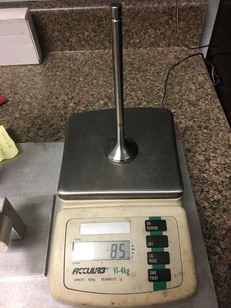
Ti exhaust valve
For an idea of size
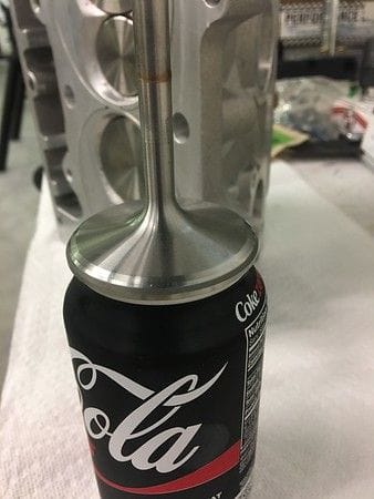
Intake valve
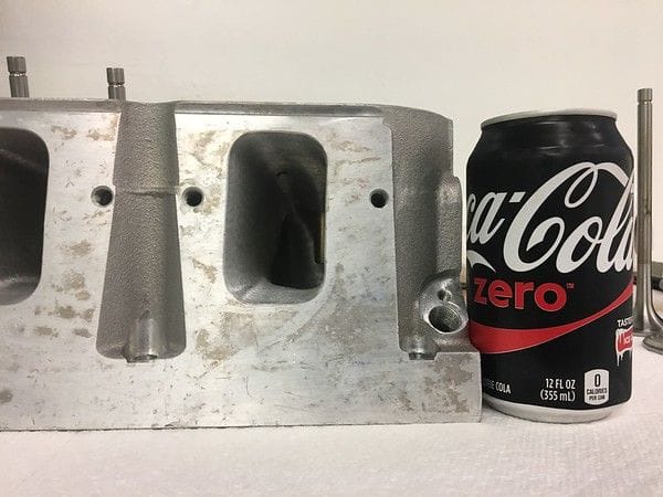
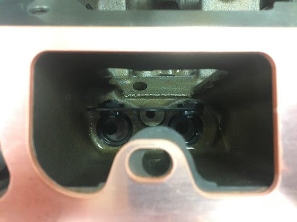
intake port
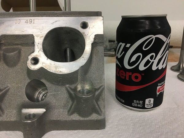
exhaust port
To keep the valves under control we are using a triple valve spring from PSI. High RPM, high boost, and a solid roller cam is going to require a higher than "normal" performance valve spring. Seat pressure on these springs is a little over 450 lbs which is more open pressure than what you will find in a common place hyd cam kit for your street car. Open pressures can exceed 1200 lbs and the springs are able to support over 1" of lift without coil bind issues. Here you can see them apart compared to a popular dual spring package commonly sold online. These are required for the extreme lift, rpm, and boost even when using a very light valve as we have shown above.
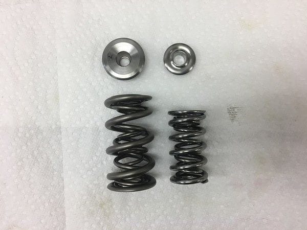
Assembled springs
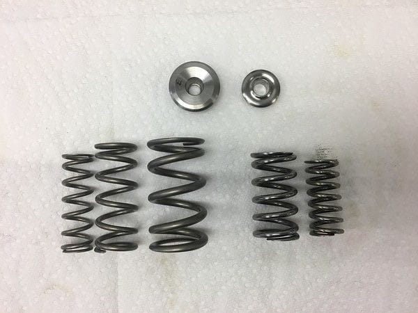
Springs apart
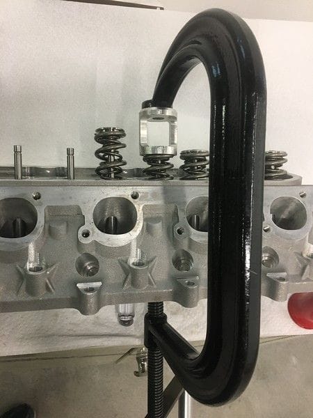
Big springs....require big spring compressors as well.
Once the heads are cleaned, springs setup for height, they are assembled and will be installed.
Head gaskets are solid copper with a o-ring wire in the head, and receiver groove in the block surface. Because of this, we will install each head and torque to spec and let it sit over night to emboss the groves into the gasket. Each gasket is then marked, and removed until time to be installed for good.
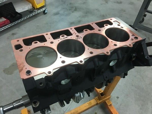
Head gasket waiting to be embossed
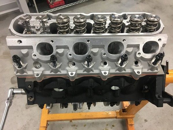
First head going on
You might notice that #1 has checking springs on it. Since we will have to remove the head after this procedure we are going to take this time to accurately measure piston to valve clearance to make sure all beginning calculations were right and we will not have any interference issues. We are also going to take this time to check for accurate pushrod measurements. Since we left the lifters in the block for #1 we are going to mock up the entire valve train for this cylinder and rotate the engine to make sure the pushrod length is correct and within the adjustment of the rocker arms.
Once the head has been removed, the lifters are cleaned, and oiled before installing into the block for good.
Lifters going in
Once the lifters are installed, and the gaskets embossed we take to bolting the heads down for the final time.
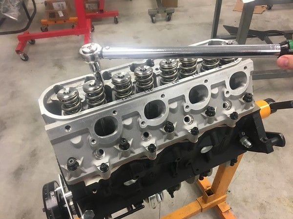
Cylinder head install for final time
Rocker arm assembly time
Since we had taken the time to measure the pushods during the head gasket seating procedure they arrived without much delay in doing assembly for the final time. We checked for not only the correct length but also for the correct diameter. Again, due to the extreme valve spring loads, using a strong pushrod to fight against deflection in the valve train is very important. Intake and exhaust lengths are different as in most engines of this caliber, but we also strive to use a much larger diameter than most might think of. These are a dual taper 1/2" to 7/16" with dual tool steel tips to make sure they clear all components involved.
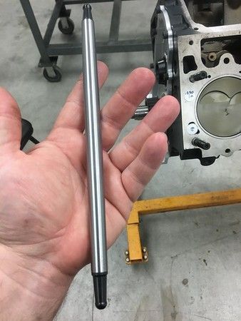
Custom double taper pushrods with tool steel tips on both ends.
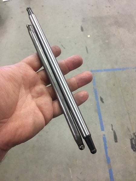
Compared to a "beefy" stock LS7 3/8 pushrod
The pushrods will be operating a set of adjustable Jesel shaft mounted rocker arms setup for the LSx DR cylinder heads.


You are going to be quick to notice that those two arms do not look the same....and they are not. There are two main reasons we chose to run a dual style rocker. Cost and weight. Because the loads on the intake rocker arm will not be nearly as high as the exhaust, which is opening against high cylinder pressure, we can run a lighter aluminum bodied arm. The aluminum arms also reduce cost vs running steel arms on both intake and exhaust side.
Prior to install, each rocker is inspected, cleaned, and oiled at all pivot points. Assembly lube placed at both ends of the pushrods and at the bottom cup of the adjuster on the rocker so nothing is dry on start up.

Here you can get a good idea of just how much these rockers are going to have to move. You will also notice how much you need to take care of your clearances, as some are very tight, as in the intake rocker to pushrod.


Once all are installed we will spin the engine over by hand a few times and remove a couple rockers to check for a wear pattern on the tops of the valves.

While we did not go into detail on the cam specs, RPM range, head flow numbers....all of these are important to work together. Doing your math prior to ordering parts is a good way to get started but testing is the only real proven way to know for sure you are not going to have issues with your build. This in many ways is why it is very important to work with your engine builder on your project so both parties know exactly how the engine is going to be used, what should be expected of it both in performance and maintenance schedules. Pick and engine builder that will be honest with you and not tell you what you want to hear but what is right. Picking a good engine builder from the start should go without saying....
Because this is going to encompass the valves, rockers, heads, gaskets.....this update is going to have a lot of material thrown at you all at one time. So much of the next steps tie into the next part more so than earlier so bare with us.
The cylinder heads and valve train can sometimes turn into a mystery for a lot of people on their builds. There are a number of steps that you can take to try and cover as many basis as you can if you are trying something new but it does boil down to having a combo that is proven and tested to work together. Picking pieces here and there sometimes can result in very poor performance even though each individual part can be quite good....they just might not work well together.
Some points of this section I will not go into great deal with spec wise as to this particular build.
So off we go..
Camshaft
Camshaft installed
For our purposes within the LS market there are really only two types of camshafts. Solid roller or Hydraulic roller. As you have seen in prior updates on the lifters you already know this is going to be a solid roller profile camshaft. Some of you might know that you can also pick from a traditional style babbitt bearing or go to a roller bearing. You can typically also go larger on the camshaft diameter. In this case we went with the traditional style babbitt but did increase the core size up from 55mm to 60mm to increase the camshaft stiffness due to the pressures it is going to see.
Cam Drive
There are a number of ways the camshaft can be driven and timed to the crankshaft. The most common way for a traditional American V8 has been the timing chain. Of course there are different styles from non adjustable to adjustable, single or dual row chains. There is the every popular gear drive with the hot rodders that love the whine of the gears at speed and almost zero slack in the system. However with high RPM and race use engines, the belt is still one of the best ways to go. These tend to dampen out some harmonics and give an almost shock absorber application when running extremely high spring pressures. Because of the solid roller, high spring pressures, high RPM use and the face that we would like to be able to make adjustments to cam timing....a Jesel belt drive will be used on this engine.
Jesel belt drive front cover
You can see the bolt pattern of the Jesel is exactly the same as any LS front cover so the system can be used on almost any number of LS engine blocks, given you take the time to machine the front of the block for clearance for the cover to fit.
There are quite a number of parts included in the system.
Jesel belt drive
- front cover
- crank drive pulley
- cam adjustable pulley
- belt
- cam plate with thrust bearing
- hardware
Below you will see the final assembly installed waiting on the balancer.
Belt drive installed along with ATI drive hub
Now you might be asking why not run a belt all of the time? Well they do stretch over time and will have to be serviced. In this case they are exposed to the elements so street use where rocks and debris can damage the belt and pulleys would not make it the best choice for a daily driver. For most builds out there, a chain is still the best of both worlds. The other piece to notice when applying this to an LS engine, there is zero room for an "internal" oil pump. When using the Jesel the engine must be a dry sump oiling system.
Timing is very critical on not only degreeing in the cam but also the balancer. Before the driver side head is placed onto the engine, we must make sure the timing marks on the balancer are correct and that we have the cam timing that we would like to see and locked in.
Cylinder Heads
Here we could devote an entire book on, so we are not going to go into who's head is better than who's or the details of head porting. Cylinder heads in many ways are one key item in to knowing how much an engine will make, at least NA wise. The size of the intake valve, the intake runner size, and how much CFM it can actually flow will give you a good idea of what the potential of the engine is. Air flow velocity must also be taken into account along with the total air flow. This one is slightly different in that we are force feeding it, but never the less, the heads have to be able to flow air. So lets look at a few key components that make this one different. The heads we are using in this build are a 6 bolt GM LSx DR head ported and worked over by Greg Good with final assembly done here in house.
Bronze intake guide, steel exhaust guide
Because this engine is going to be forced induction, and a turbo at that, there is going to be a lot of exhaust heat in the head. A bronze guide will just not hold up to very high EGT's so in this case a steel valve guide is used. You will also notice a really small o-ring...that is pretty much the only valve seal that will be used. Since the engine will never see street use and will be torn down for rebuilds more often than your street car, the traditional seals are left off. This also allows slightly more oil to keep the valves lubed and cooled.
Both the intake and exhaust valves are made from solid Titanium and are longer than normal to accept the big springs and adjustable rocker arms that will be used.
Ti intake valve
Ti exhaust valve
For an idea of size
Intake valve
intake port
exhaust port
To keep the valves under control we are using a triple valve spring from PSI. High RPM, high boost, and a solid roller cam is going to require a higher than "normal" performance valve spring. Seat pressure on these springs is a little over 450 lbs which is more open pressure than what you will find in a common place hyd cam kit for your street car. Open pressures can exceed 1200 lbs and the springs are able to support over 1" of lift without coil bind issues. Here you can see them apart compared to a popular dual spring package commonly sold online. These are required for the extreme lift, rpm, and boost even when using a very light valve as we have shown above.
Assembled springs
Springs apart
Big springs....require big spring compressors as well.
Once the heads are cleaned, springs setup for height, they are assembled and will be installed.
Head gaskets are solid copper with a o-ring wire in the head, and receiver groove in the block surface. Because of this, we will install each head and torque to spec and let it sit over night to emboss the groves into the gasket. Each gasket is then marked, and removed until time to be installed for good.
Head gasket waiting to be embossed
First head going on
You might notice that #1 has checking springs on it. Since we will have to remove the head after this procedure we are going to take this time to accurately measure piston to valve clearance to make sure all beginning calculations were right and we will not have any interference issues. We are also going to take this time to check for accurate pushrod measurements. Since we left the lifters in the block for #1 we are going to mock up the entire valve train for this cylinder and rotate the engine to make sure the pushrod length is correct and within the adjustment of the rocker arms.
Once the head has been removed, the lifters are cleaned, and oiled before installing into the block for good.
Lifters going in
Once the lifters are installed, and the gaskets embossed we take to bolting the heads down for the final time.
Cylinder head install for final time
Rocker arm assembly time
Since we had taken the time to measure the pushods during the head gasket seating procedure they arrived without much delay in doing assembly for the final time. We checked for not only the correct length but also for the correct diameter. Again, due to the extreme valve spring loads, using a strong pushrod to fight against deflection in the valve train is very important. Intake and exhaust lengths are different as in most engines of this caliber, but we also strive to use a much larger diameter than most might think of. These are a dual taper 1/2" to 7/16" with dual tool steel tips to make sure they clear all components involved.
Custom double taper pushrods with tool steel tips on both ends.
Compared to a "beefy" stock LS7 3/8 pushrod
The pushrods will be operating a set of adjustable Jesel shaft mounted rocker arms setup for the LSx DR cylinder heads.
Aluminum 1.8 ratio intake rocker arm
Steel 1.8 ratio exhaust rocker arm
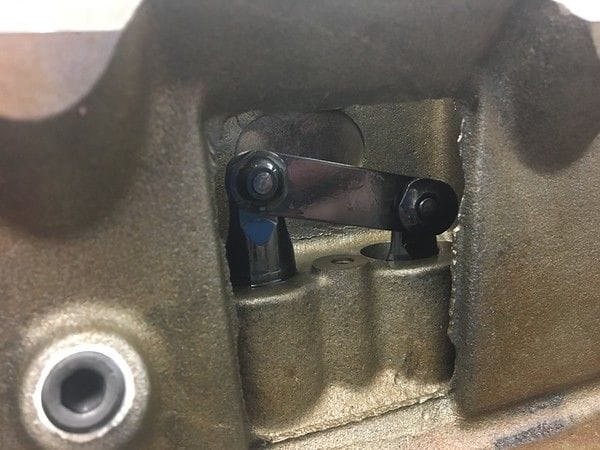
You are going to be quick to notice that those two arms do not look the same....and they are not. There are two main reasons we chose to run a dual style rocker. Cost and weight. Because the loads on the intake rocker arm will not be nearly as high as the exhaust, which is opening against high cylinder pressure, we can run a lighter aluminum bodied arm. The aluminum arms also reduce cost vs running steel arms on both intake and exhaust side.
Prior to install, each rocker is inspected, cleaned, and oiled at all pivot points. Assembly lube placed at both ends of the pushrods and at the bottom cup of the adjuster on the rocker so nothing is dry on start up.
Rocker arms installed, ready for lash
Here you can get a good idea of just how much these rockers are going to have to move. You will also notice how much you need to take care of your clearances, as some are very tight, as in the intake rocker to pushrod.
exhaust at full lift
intake at full lift.
Once all are installed we will spin the engine over by hand a few times and remove a couple rockers to check for a wear pattern on the tops of the valves.
Wear pattern right in the middle, even with over 0.9xx of lift
While we did not go into detail on the cam specs, RPM range, head flow numbers....all of these are important to work together. Doing your math prior to ordering parts is a good way to get started but testing is the only real proven way to know for sure you are not going to have issues with your build. This in many ways is why it is very important to work with your engine builder on your project so both parties know exactly how the engine is going to be used, what should be expected of it both in performance and maintenance schedules. Pick and engine builder that will be honest with you and not tell you what you want to hear but what is right. Picking a good engine builder from the start should go without saying....